Components
Bill of materials
TerraSync's circuit uses a minimal set of components — a photoresistor for ambient sensing, a push button for focus state control, and three LEDs to produce warm, diffused light under the dome.
Schematic
Circuit design
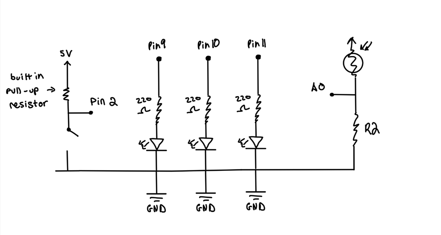
All components share a common ground rail. The button uses the Arduino's built-in INPUT_PULLUP — no external pull-down needed. The photoresistor is paired with a 10KΩ resistor to form a voltage divider, and each LED has its own 220Ω current-limiting resistor.
Resistor calculations
Ohm's law
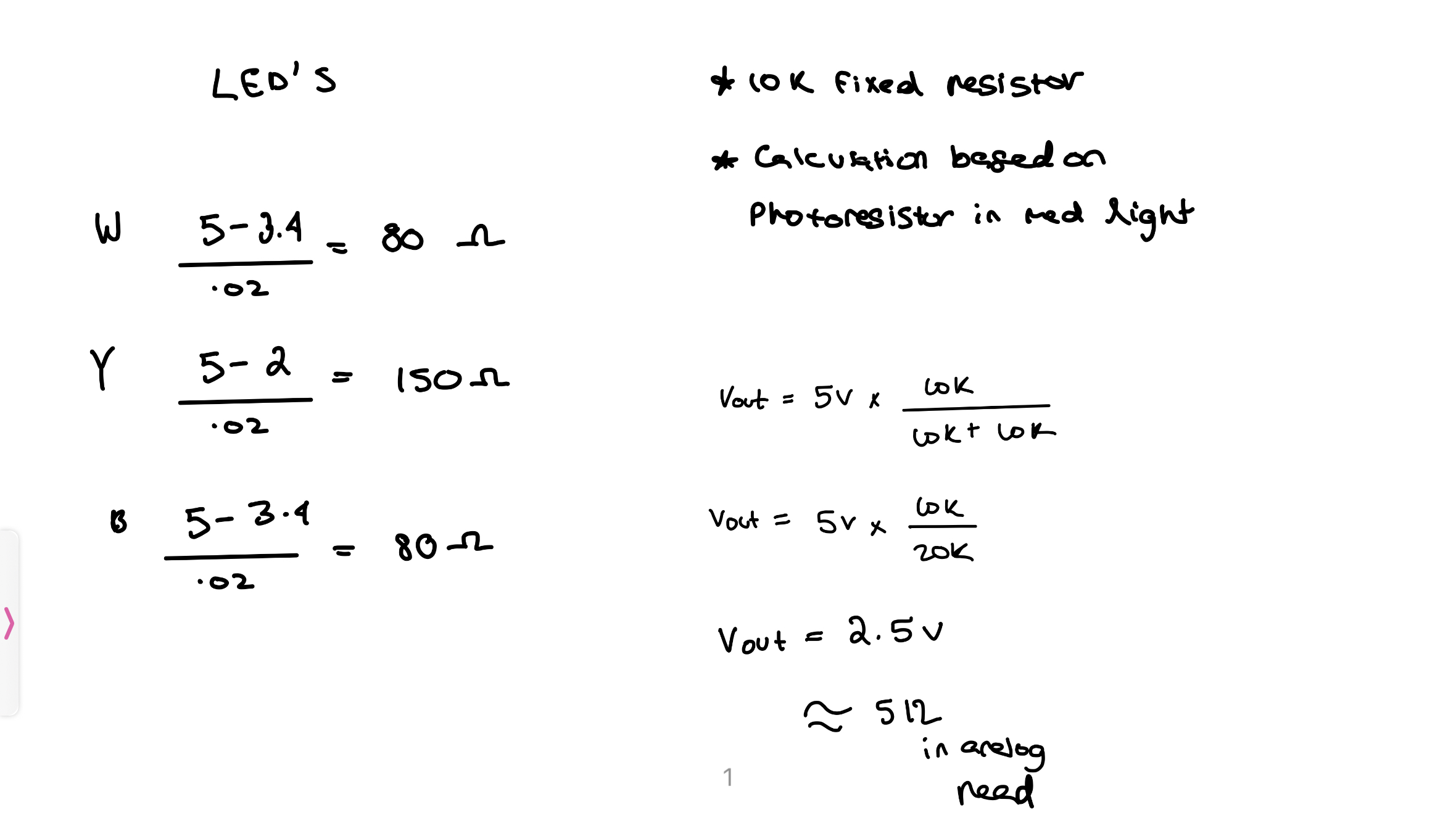
Each LED required a current-limiting resistor sized to keep the LED safe without sacrificing too much brightness. Using R = (Vs − Vf) / I, 220Ω was the closest standard value that kept current safely under the LED's rated limit.
| LED | Forward Voltage (Vf) | Target Current | Calculated R | Chosen R |
|---|---|---|---|---|
| White | 3.2 V | 20 mA | ~90 Ω | 220 Ω |
| Yellow | 2.0 V | 20 mA | ~150 Ω | 220 Ω |
| Blue | 3.2 V | 20 mA | ~90 Ω | 220 Ω |
220Ω was chosen for all three LEDs because it's the nearest standard value that keeps current safely within spec for each LED type — and using the same value across all three simplified the build without any meaningful tradeoffs in brightness.
Arduino firmware
Sensor logic & serial output
The firmware reads both inputs on each loop cycle, maps the photoresistor value to LED brightness (inverting so darkness = bright LEDs), then sends a compact serial string for Unity to parse. A 20ms delay reduces debounce noise on the button.
/*
  Valentina Filizola
  TerraSync — HCDE 439 Final Project
*/

// Pin definitions
const int lightSensorPin = A0;   // photoresistor
const int buttonPin = 2;          // button

// LED pins
const int led1 = 9;    // white LED
const int led2 = 10;   // yellow LED
const int led3 = 11;   // blue LED

void setup() {
  Serial.begin(9600);                   // match Unity serial speed
  pinMode(buttonPin, INPUT_PULLUP);     // built-in pull-up, no ext. resistor
  pinMode(led1, OUTPUT);
  pinMode(led2, OUTPUT);
  pinMode(led3, OUTPUT);
}

void loop() {
  int lightValue  = analogRead(lightSensorPin);  // 0–1023
  int buttonState = digitalRead(buttonPin);

  int buttonPressed = (buttonState == LOW) ? 1 : 0;

  // Constrain range — LEDs dim earlier, stay bright in darkness
  int constrainedLight = constrain(lightValue, 0, 600);

  // Invert: dark room → full brightness
  int brightness = map(constrainedLight, 0, 600, 255, 0);

  analogWrite(led1, brightness);
  analogWrite(led2, brightness);
  analogWrite(led3, brightness);

  // Serial output format Unity expects: "L:512,B:0"
  Serial.print("L:");
  Serial.print(lightValue);
  Serial.print(",B:");
  Serial.println(buttonPressed);

  delay(20);   // debounce buffer
}
In operation
Circuit behavior
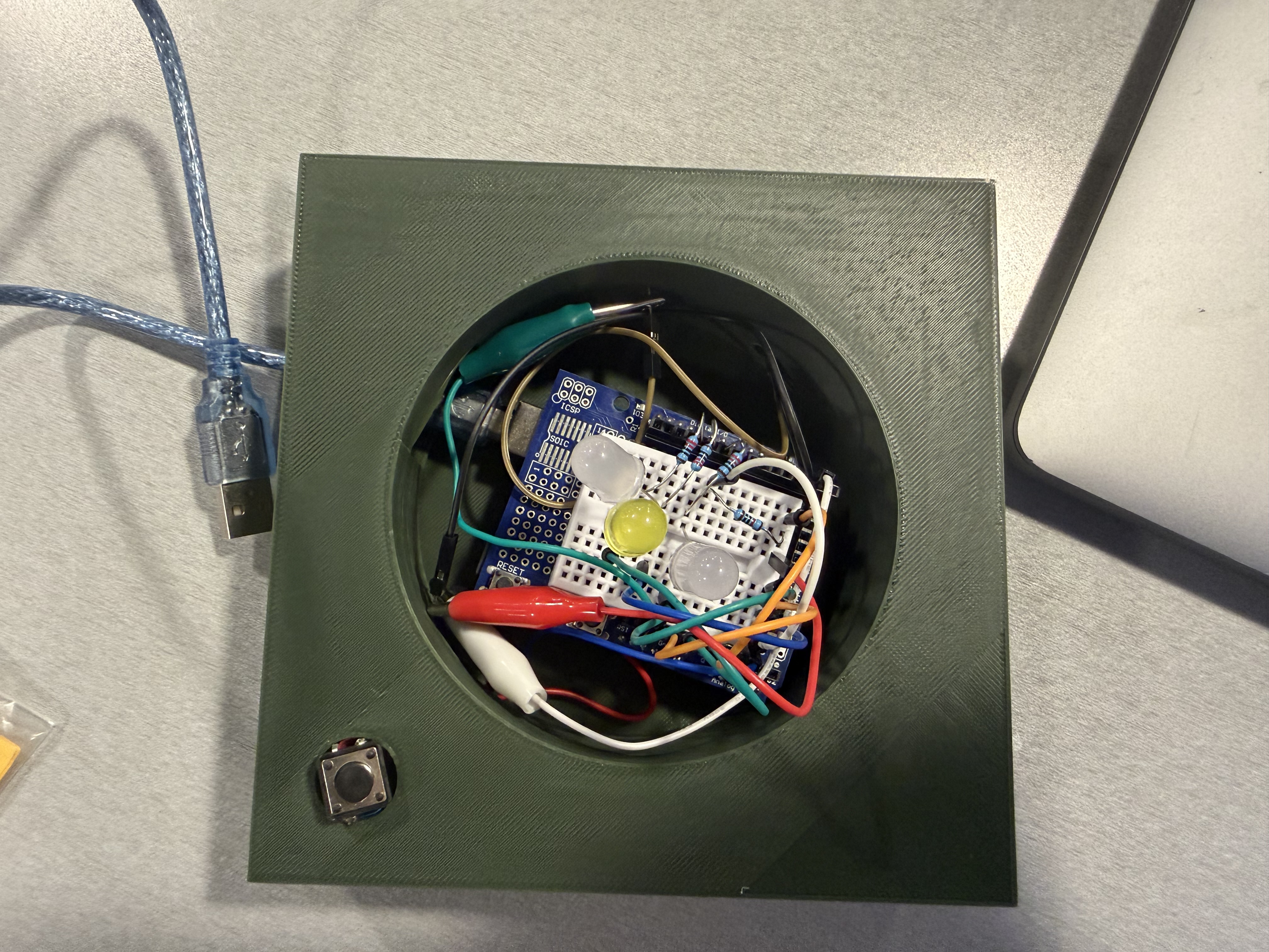
The GIF below shows the full sensing loop in action — photoresistor driving LED brightness while the button state is transmitted to Unity. Covering the sensor dims the room, triggering the LEDs to glow and shifting the Unity scene to its night state.